We can't find the internet
Attempting to reconnect
Something went wrong!
Hang in there while we get back on track
The Improved Howland Current Pump
The "Improved" Howland Current Pump is a type of current pump capable of injecting current:
- in either direction (source or sink)
- to a grounded load
Intuitively, this operational amplifier configuration is trying to move it's output such that the voltage across the load will vary with the change in the load, resulting in a constant current output. The following StackExchange discussion is useful in understanding this intuition.
Texas Instruments has a great application report covering the dynamics of the system, choice of of passive of components as well as the basic history of the circuit.
As a supplement to their article, we will be deriving the relationship between $I_L$ and $V_{in}$.
Big thanks to Wei Xuan for reviewing and sanity checking the analysis!
Analysis
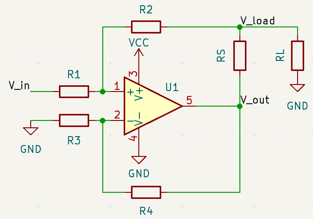
Applying Kirchoff's Voltage Law, we can deduce the values of $V_+$ and $V_-$:
$$V^+ = \frac{R_1}{R_1 + R_2}(V_{load} - V_{in})$$
$$V^- = \frac{R_3}{R_3 + R_4}(V_{out})$$
An operational amplifier with negative feedback will attempt to balance its 2 inputs:
$$V^+ = V^-$$
$$\frac{R_1}{R_1 + R_2}(V_{load} - V_{in}) = \frac{R_3}{R_3 + R_4}(V_{out})$$
We can simplify this equation by applying the following assumption:
$$R_1 = R_3, R_2 = R_4$$
$$(V_{out} - V_{load}) = -V_{in}$$
The above equation relates $V_{in}$ with $V_{load}$ and $V_{out}$, with the resistors in the feedback paths cancelling out.
Let's observe the flow of current at the point $V_{load}$. The current out of the amplifier through $R_S$ will be the same as the current through $R_L$, assuming feedback current through $R_2$ and $R_4$ is negligible. Formulating this as an equation:
$$I_L = \frac{V_{out} - V_{load}}{R_S}$$
Substituting the earlier $V_{in}$ equation into the above:
$$I_L = -\frac{V_{in}}{R_S}$$
From this, we can see that $R_S$ controls $I_L$, assuming all resistors are balanced.
Food for thought
We can find the "true" relationship between $I_L$ and $V_{in}$ by not using the resistance matching assumption. This would be beneficial in studying the impact of unbalanced resistor pairs on the functionality of the circuit.